
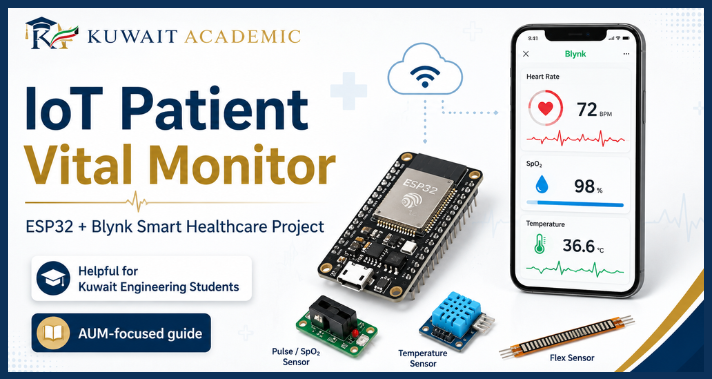
IoT Patient Monitoring System: The Internet of Things is transforming how we communicate with everyday objects, gather data and remotely track systems. In the field of healthcare technology, many sensors can help to observe critical parameters continuously and alert in a timely way when certain conditions are met.
In this project, we created an IoT Patient Vital Signs Monitoring System with ESP32 and Blynk. The aim of the prototype is to investigate how embedded systems, sensors, wireless communication via Wi-Fi and a dashboard connected to cloud-based software can be integrated into a single, real-life engineering project.
The system, built around the ESP32 microcontroller, incorporates optical sensing capabilities for pulse, temperature measurement, and breathing movement estimation, and for the larger reported system, fall detection. The collected information can be displayed remotely through the Blynk IoT platform, while green and red LEDs provide simple local status indications.
The embedded programming, sensor interfacing, IoT communication, mobile dashboards, hardware troubleshooting, threshold-based alerts and system testing are all important technical areas that are integrated into this project, making it very relevant to the engineering education in Kuwait.
Important note: This is an educational engineering prototype. It is not a certified medical device and must not be used for diagnosis, treatment, emergency decisions, or replacement of professional healthcare equipment.
Why We Developed This IoT Patient Monitoring Project
This blog describes the entire design and the lessons learned when implementing this in detail for students working on Embedded systems projects, AUM Computer Engineering projects, or smart healthcare monitoring systems for IoT project in Kuwait.
Traditional health measurements are often taken at specific times. An individual can go to a clinic, use an independent instrument or record the readings by hand. In a prototype solution, an IoT sensor gathers data, a microcontroller processes it, and only some of the data is pushed back over the internet to a remote dashboard, presenting a new engineering concept.
The aim of our project report was especially linked to the continuous monitoring issues in Kuwait. The report took into account the needs of elderly persons, patients who might have trouble visiting the hospital often, and where remote observation might be useful. The proposed system was therefore centered on a low-cost, and accessible prototype architecture.
A key engineering challenge was to:
Can multiple sensors be connected to a single ESP32, processed in real-time, displayed on another location, and integrated with the capability of automatic alert logic?
This question resulted in the creation of the IoT Vital Monitor.
IoT Patient Monitoring Project Objectives
The primary goal is to create a sort of prototype of a connected monitoring that will be able to integrate multiple functions within one system. The ESP32 serves as the central controller in this project.
The project had the following objectives:
In this prototype, the ESP32 performs several tasks:
- Reading data from the sensors on the ESP32
- Reading the finger or optical signal with the MAX30105
- Reading the temperature of MLX90614
- Using a flex sensor to measure breathing movement
- Implementing fall detection with the MPU6050
- The ability to send and receive some of the values via Wi-Fi technology
- Showing data on a Blynk dashboard
- Providing local LED indications
- Providing an alarm when set conditions are met
- Maintaining the prototype as a comprehensible and teachable prototype
Components Table
| Component | Role in the Project |
|---|---|
| ESP32 | Main controller and Wi-Fi communication |
| MAX30105 | Optical sensing and finger-presence |
| MLX90614 | Infrared temperature sensing |
| Flex Sensor | Chest movement detection for breathing-count |
| MPU6050 | Fall-detection |
| Green LED | Normal-status indication |
| Red LED | Alert-status indication |
| Blynk | Remote dashboard and event notifications |
| Breadboard | Prototype assembly |
| Jumper Wires | Electrical connections |
| Resistors | LED current limiting and sensor interfacing |
Block Diagram
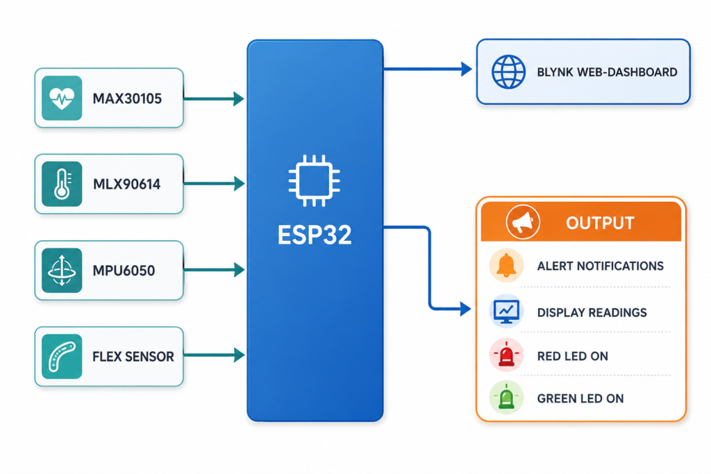
The block diagram depicts the basic architecture of IoT Patient Monitoring System with ESP32 and Blynk. Each sensor, including MAX30105, MLX90614, MPU6050 and flex sensor, are connected to the ESP32 microcontroller. ESPY32 is the heart of the project, it collects data from all sensors related to the health of the person. Once reading is done on sensors, the ESP32 transfers sensor data via Wi-Fi to the Blynk Web Dashboard.
Some of the outputs of the system are also valuable like alert notification, live display reading, red LED sign for abnormal condition and green LED sign for normal condition. This block diagram would assist students to gain an understanding of the interconnection of all the hardware and software components in the total IoT healthcare project.
Flow Chart
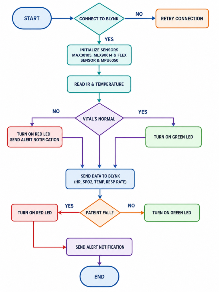
The working process of the IoT Patient Monitoring System is given in the step by step manner using the flow chart. The first step of the system is to link the ESP32 to the Blynk platform. If this fails to connect the system will try again until it makes a successful connection. Once connected, the sensors: MAX30105, MLX90614, flex sensor, and MPU6050 are initialized.
Then it reads the IR and temperature value, and checks if the patient’s vital signs are normal, the green LED is turned on when the patient’s vital signs are normal, and the red LED is turned on with an alert message when the patient’s vital signs are abnormal. The health data such as heart rate, SpO₂, temperature, and respiratory rate is sent to Blynk for remote monitoring. The system also monitors for the patient’s fall and provides an alert if it detects a fall.
Connection Diagram
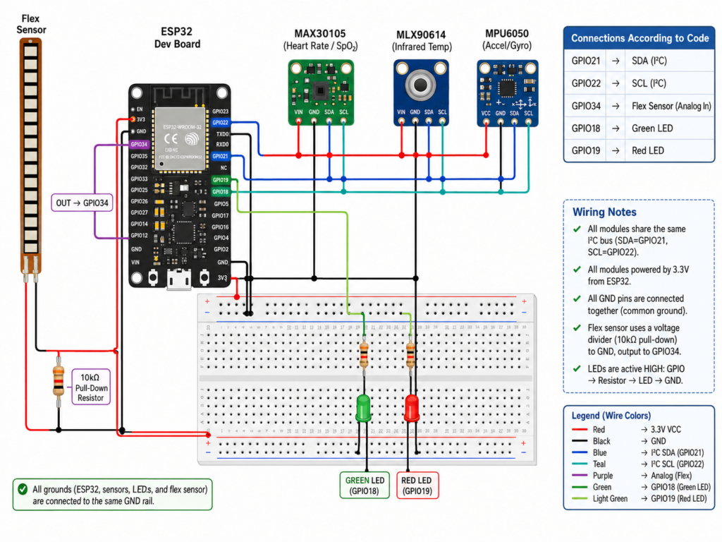
The connection diagram is a schematic that shows the various connections between the different devices and components used in the IoT Patient Monitoring System. In this circuit, the MAX30105, MLX90614 and MPU6050 sensors share the same I2C communication pins, with GPIO21 connected to the I2C SDA and GPIO22 connected to the I2C SCL. The green LED is connected to GPIO18, red LED is connected to GPIO19, and flex sensor is connected to GPIO34 which is used as an analog input to track breathing movement.
Normal patient condition is indicated by the green LED, and when abnormal vital signs or alert conditions are detected, the red LED will turn on. For engineering students in Kuwait and AUM, this diagram is a practical example of the connection of sensors and indicators, power and ground connections for a project involving healthcare monitoring using the ESP32.
Working Principle
This section shows the complete working principle of each component:
Understanding the working of MAX30105
The MAX30105 is an optical particle and pulse-related sensing device. In the shared firmware, the program reads the infrared channel using:
irValue = particleSensor.getIR();The program then checks whether the IR value exceeds a threshold:
if (irValue > 50000)
{
  heartRate = random(70,95);
  spo2 = random(95,99);
}
else
{
  heartRate = 0;
  spo2 = 0;
}
Temperature Measurement with MLX90614
The MLX90614 is an infrared temperature sensor. In the code, temperature is read using:
bodyTemp = mlx.readObjectTempC();This value is then:
- printed to the Serial Monitor
- sent to Blynk
- checked by the alert logic
The MLX90614 communicates over I2C, which allows it to share the ESP32’s SDA and SCL communication lines with compatible devices.
In the following setup, I2C is initialized as:
Wire.begin(21,22);This means:
- GPIO 21 is used for SDA
- GPIO 22 is used for SCL
Respiratory Movement Estimation Using a Flex Sensor
One creative part of this project is the use of a flex sensor to detect bending movement associated with chest motion.
The flex sensor is connected to:
#define FLEX_PIN 34The ESP32 reads it using:
flexValue = analogRead(FLEX_PIN);The program then compares the reading against a threshold:
if (flexValue > flexThreshold && !bendDetected)
{
  respiratoryRate++;
  bendDetected = true;
}
Once the value drops sufficiently, the system resets the state:
if (flexValue < flexThreshold - 50)
{
  bendDetected = false;
}
The purpose of bendDetected is to reduce repeated counting while the flex sensor remains above the threshold. This is a simple form of state control.
The -50 difference also introduces a basic hysteresis-like behavior. Without such separation, noisy readings close to the threshold could cause repeated transitions.
Green and Red LED Alert System
The prototype uses two LEDs:
#define GREEN_LED 18
#define RED_LED 19
The intended behavior is simple:
- green LED = conditions are within the accepted logic
- red LED = at least one alert condition has been triggered
The alert block checks several conditions:
if (heartRate < minBPM || heartRate > maxBPM ||
    bodyTemp > maxTemp ||
    spo2 < minSpO2 ||
    millis() > minResp && respiratoryRate < 5)
{
  digitalWrite(RED_LED, HIGH);
  digitalWrite(GREEN_LED, LOW);
  Blynk.logEvent("health_alert",
                 "Abnormal Vital Signs Detected!");
}
else
{
  digitalWrite(RED_LED, LOW);
  digitalWrite(GREEN_LED, HIGH);
}
Blynk IoT Dashboard Integration
The project uses the Blynk IoT platform to display information remotely.
The code sends values to virtual pins:
Blynk.virtualWrite(V0, heartRate);
Blynk.virtualWrite(V1, spo2);
Blynk.virtualWrite(V3, bodyTemp);
Blynk.virtualWrite(V4, respiratoryRate);
A simple mapping is:
| Virtual Pin | Data |
|---|---|
| V0 | Heart Rate |
| V1 | SpO₂ |
| V3 | Temperature |
| V4 | Respiratory Count/Value |
Software Libraries Used
The implementation uses several libraries:
#include <WiFi.h>
#include <BlynkSimpleEsp32.h>
#include <Wire.h>
#include "MAX30105.h"
#include <Adafruit_MLX90614.h>
Why BlynkTimer Is Used
The code creates:
BlynkTimer timer;Then schedules:
timer.setInterval(2000L, sendSensorData);This means the sensor function is called approximately every two seconds without placing a long blocking delay inside the main loop.
The main loop remains simple:
void loop()
{
  Blynk.run();
  timer.run();
}
Complete Code
#define BLYNK_PRINT Serial
#define BLYNK_TEMPLATE_ID "TMPL3AsZrguRM"
#define BLYNK_TEMPLATE_NAME "PATIENT"

#include <WiFi.h>
#include <BlynkSimpleEsp32.h>
#include <Wire.h>
#include "MAX30105.h"
#include <Adafruit_MLX90614.h>

char auth[] = "YOUR_BLYNK_AUTH_TOKEN";
char ssid[] = "YOUR_WIFI_SSID";
char pass[] = "YOUR_WIFI_PASSWORD";

#define GREEN_LED 18
#define RED_LED 19
#define FLEX_PIN 34

MAX30105 particleSensor;
Adafruit_MLX90614 mlx;

long irValue;
int heartRate = 0;
int spo2 = 0;
float bodyTemp = 0;

int respiratoryRate = 0;

BlynkTimer timer;

int minBPM = 60;
int maxBPM = 100;
float maxTemp = 38.0;
int minSpO2 = 5;

int flexValue = 0;
int flexThreshold = 1550;
int minResp = 30000;

bool bendDetected = false;

void sendSensorData()
{
  irValue = particleSensor.getIR();

  Serial.print("IR Value: ");
  Serial.println(irValue);

  if (irValue > 50000)
  {
    heartRate = random(70,95);
    spo2 = random(95,99);
  }
  else
  {
    heartRate = 0;
    spo2 = 0;
  }

  bodyTemp = mlx.readObjectTempC();

  flexValue = analogRead(FLEX_PIN);


  if (flexValue > flexThreshold && !bendDetected)
  {
    respiratoryRate++;
    bendDetected = true;
  }

  if (flexValue < flexThreshold - 50)
  {
    bendDetected = false;
  }

  Serial.println("----- Patient Health Data -----");

  Serial.print("Heart Rate: ");
  Serial.print(heartRate);
  Serial.println(" BPM");

  Serial.print("SpO2: ");
  Serial.print(spo2);
  Serial.println(" %");

  Serial.print("Body Temperature: ");
  Serial.print(bodyTemp);
  Serial.println(" C");

  Serial.print("Flex Value: ");
  Serial.println(flexValue);

  Serial.print("Respiratory Count: ");
  Serial.println(respiratoryRate);

  Serial.println("-------------------------------");

  Blynk.virtualWrite(V0, heartRate);
  Blynk.virtualWrite(V1, spo2);
  Blynk.virtualWrite(V3, bodyTemp);
  Blynk.virtualWrite(V4, respiratoryRate);

  if (heartRate < minBPM || heartRate > maxBPM ||
      bodyTemp > maxTemp ||
      spo2 < minSpO2  || millis() > minResp && respiratoryRate < 5)
  {
    digitalWrite(RED_LED, HIGH);
    digitalWrite(GREEN_LED, LOW);
    Blynk.logEvent("health_alert","Abnormal Vital Signs Detected!");
  }
  else
  {
    digitalWrite(RED_LED, LOW);
    digitalWrite(GREEN_LED, HIGH);
  }
}

void setup()
{
  Serial.begin(115200);

  pinMode(GREEN_LED, OUTPUT);
  pinMode(RED_LED, OUTPUT);
  pinMode(FLEX_PIN, INPUT);
  Wire.begin(21,22);
  Blynk.begin(auth, ssid, pass);
  if (!particleSensor.begin(Wire))
  {
    Serial.println("MAX30105 not detected");
    while(1);
  }
  particleSensor.setup();
  particleSensor.setPulseAmplitudeRed(0x0A);
  particleSensor.setPulseAmplitudeGreen(0);
  if (!mlx.begin())
  {
    Serial.println("MLX90614 not detected");
    while(1);
  }
  timer.setInterval(2000L, sendSensorData);
}
void loop()
{
  Blynk.run();
  timer.run();
}
Results
The serial monitors results and working are shown below:
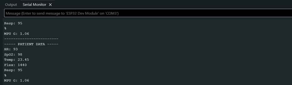
The serial monitor results show that the ESP32 is successfully reading and displaying the patient health data in real time. The output consists of the significant values like heart rate, SpO₂, body temperature, flex sensor value, respiratory count, and MPU sensor reading. The system displays heart rate around 93, SpO₂ around 98%, temp around 23.45°C, flex sensor value around 1440, and respiratory count around 95, during this test.
The readings in this file indicate that the ESP32 is successfully reading the data from the attached sensors and printing data on the serial monitor. This step is crucial during testing to ensure that the sensors, code and microcontroller are functioning properly before transmitting data to the Blynk Dashboard.
The Blynk Dashboard results are shown below:
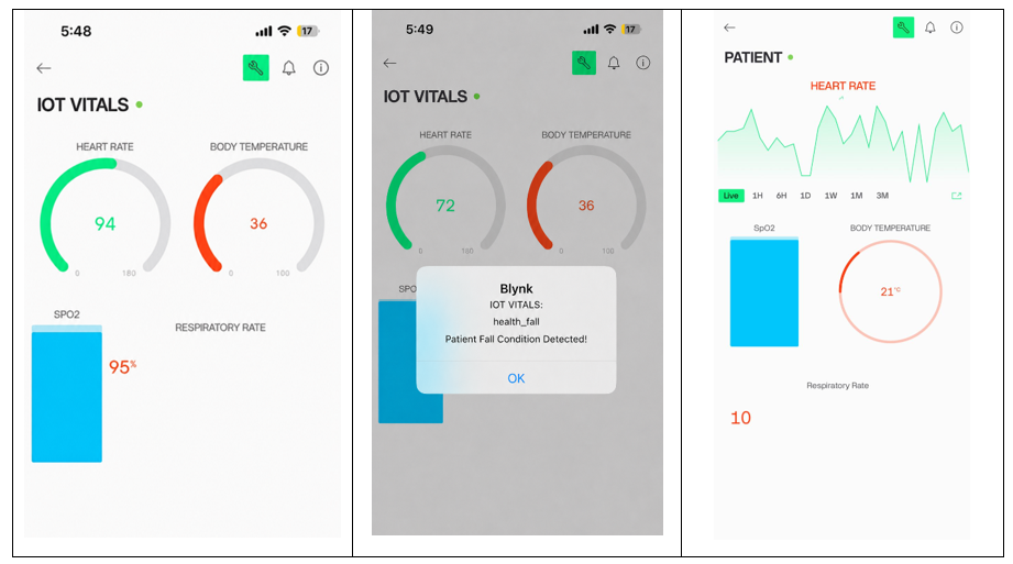
The Blynk dashboard results show that the IoT patient monitoring system is able to display health data clearly on a mobile interface. Gauges, charts, and values will display the dashboard’s heart rate, body temperature, SpO₂, and respiratory rate. The normal condition screen displays the heart rate, body temperature and SpO₂ at 94 BPM, 36°C and 95% respectively, showing the system is sending live data from the ESP32 to the Blynk app.
In the second screen, you can see that a patient fall information alert is shown, indicating that the system can alert the user when an abnormal situation occurs. The third screen shows live graph data and respiratory rate, which will help remote monitoring and easy understanding of patient health status on the dashboard.
Queries
Have questions about this IoT Patient Vital Signs Monitoring System or more information about its implementation?
We’re here to assist. If you have any questions about your project, detailed technical guidance, detailed support for hardware setup, connection of circuits, programming of the ESP32, configuration of the Blynk dashboard, integration of sensors, testing procedures, troubleshooting, or any other questions, please contact us via our Contact page.
Please submit your question and tell us a little about the kind of advice you are seeking and we will consider your request and reply. You can reach out to Kuwait Academic for any additional information or advice regarding your project works, whether for an academic project, graduation project, prototype development for embedded systems, or an IoT-based application.
