
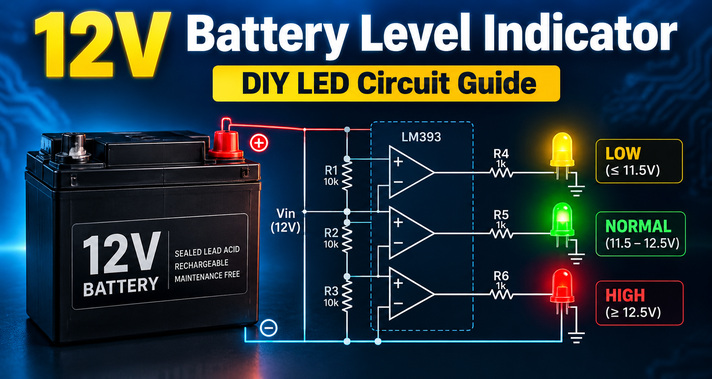
Monitoring battery voltage is essential for keeping battery-powered devices operating reliably. Whether you are working on an electronics project, a backup power system, or a DIY battery-powered device, knowing when the voltage is too low or unusually high can help prevent unexpected shutdowns and equipment problems.
A 12V battery level indicator circuit offers a simple and affordable way to monitor battery voltage without requiring a digital display or microcontroller. Using three LEDs, operational amplifiers or voltage comparators, and a few basic electronic components, you can build a circuit that provides instant visual feedback about battery voltage.
In this guide, you will learn how a battery range indicator works, which components are required, how to calculate voltage thresholds, and how to test the circuit.
What Is a Battery Level Indicator Circuit?
A battery level indicator circuit is an electronic system that monitors battery voltage and displays its condition through visual indicators. Unlike a voltmeter, which provides a numerical voltage reading, a basic LED battery indicator divides the measured voltage into predefined ranges.
A three-LED system typically uses:
- Yellow LED: Indicates that battery voltage is below the selected lower threshold.
- Green LED: Shows that voltage is within the normal operating range.
- Red LED: Warns that voltage has exceeded the selected upper threshold.
This arrangement allows users to recognize voltage conditions quickly without interpreting numerical measurements. However, battery voltage does not always indicate the exact remaining battery capacity. The relationship depends on battery chemistry, temperature, charging conditions, and connected loads.
How Does a 12V Battery Level Indicator Work?
The working principle of a battery range indicator is based on voltage comparison. The circuit continuously measures battery voltage and compares it against predetermined reference voltages.
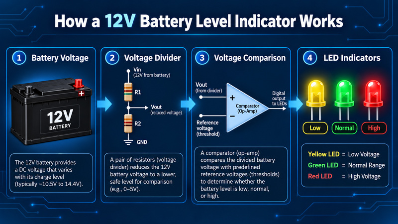
A typical system contains three main functional sections.
1. Battery Voltage Measurement
A resistor-based voltage divider reduces the battery voltage to a suitable level for comparison. This is important because comparator inputs have specified operating limits, and the measured voltage must remain within those limits. The reduced voltage represents the actual battery voltage proportionally.
2. Voltage Comparison
Operational amplifiers configured as comparators, or dedicated voltage comparator ICs, evaluate the measured voltage against reference values. When the measured voltage crosses a threshold, the comparator output changes state. The circuit then determines whether the battery is operating below, between, or above the selected limits.
3. LED Status Indication
The comparison results control three LEDs.
| Battery condition | LED activated | Meaning |
|---|---|---|
| Below lower threshold | Yellow | Low voltage |
| Between thresholds | Green | Normal voltage |
| Above upper threshold | Red | High-voltage warning |
The indicator logic should ensure that only the LED corresponding to the current voltage range remains illuminated.
Components Required for a 12V Battery Indicator
Building a basic battery indicator requires relatively inexpensive electronic components.
The main components include a 12V battery or adjustable DC supply, three LEDs, comparator circuitry, fixed resistors, a variable resistor, and a push-button switch.
A voltage divider scales the battery voltage, while a resistor network establishes the reference levels.
A variable resistor, commonly identified as RV1, makes it possible to fine-tune the switching thresholds.
Each LED also requires a current-limiting resistor to prevent excessive current flow.
For prototyping, you will need a breadboard, connecting wires, and a digital multimeter.
A dedicated comparator such as an LM339 may be suitable, provided its supply, input-voltage range, and output requirements are considered. Its open-collector outputs require appropriate connections and pull-up arrangements.
Understanding Voltage Threshold Calculations
Voltage thresholds determine when the indicator changes from one LED to another.
Two important values must be defined:
Lower threshold (Vlow): The voltage below which the yellow LED should activate.
Upper threshold (Vhigh): The voltage above which the red LED should activate.
When the measured voltage falls between these values, the green LED should illuminate.
Calculating the Voltage Divider
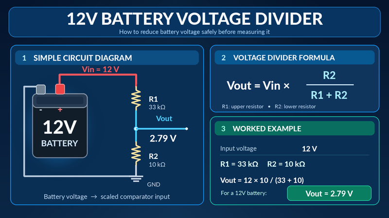
A simple voltage divider consists of two series resistors.
The output voltage is calculated using:
Vout = Vin × R2 / (R1 + R2)
Where:
- Vin is the battery voltage.
- R1 is the upper resistor.
- R2 is the lower resistor.
- Vout is the voltage supplied to the comparison circuit.
For example, consider R1 = 33 kΩ and R2 = 10 kΩ.
When the battery voltage is 12V:
Vout = 12 × 10 / (33 + 10) = 2.79V
The comparator therefore receives approximately 2.79V rather than the full 12V.
Suppose the selected battery thresholds are 11.8V and 14.6V. With this divider, their corresponding comparison voltages would be approximately 2.74V and 3.40V.
These values are illustrative, not universal battery safety limits. Actual thresholds must be selected according to the battery chemistry, manufacturer’s specifications, and whether the battery is charging or discharging.
A stable reference supply is also important because reference voltages should not simply change proportionally with the battery voltage being measured.
How to Build a 12V Battery Level Indicator Circuit in Proteus
The following process explains how to design and assemble a three-LED battery monitoring system in Proteus.
Step 1: Prepare the Power Supply
- Start with a suitable 12V DC power source.
- Connect the positive supply terminal to the circuit through a switch, and establish a common ground connection.
- A momentary push-button allows the indicator to operate only while pressed, reducing unnecessary battery consumption. For continuous monitoring, a maintained switch may be more appropriate.
Step 2: Assemble the Voltage Divider
- Connect two resistors in series between the monitored battery voltage and ground.
- Take the divided voltage from the junction between the resistors.
- This measured signal will be used by the comparator stages.
- Verify the divided voltage with a multimeter before connecting sensitive components.
Step 3: Configure the Comparators
- The comparator circuit determines which voltage range is active.
- One threshold comparison identifies low voltage, while another identifies voltage above the upper limit.
- A third comparator stage or suitable output logic can be used to produce the required three-LED indication.
- For an ideal three-state indicator, the green LED must activate only when the battery voltage lies between the two thresholds.
- The exact connections depend on the comparator IC and output configuration.
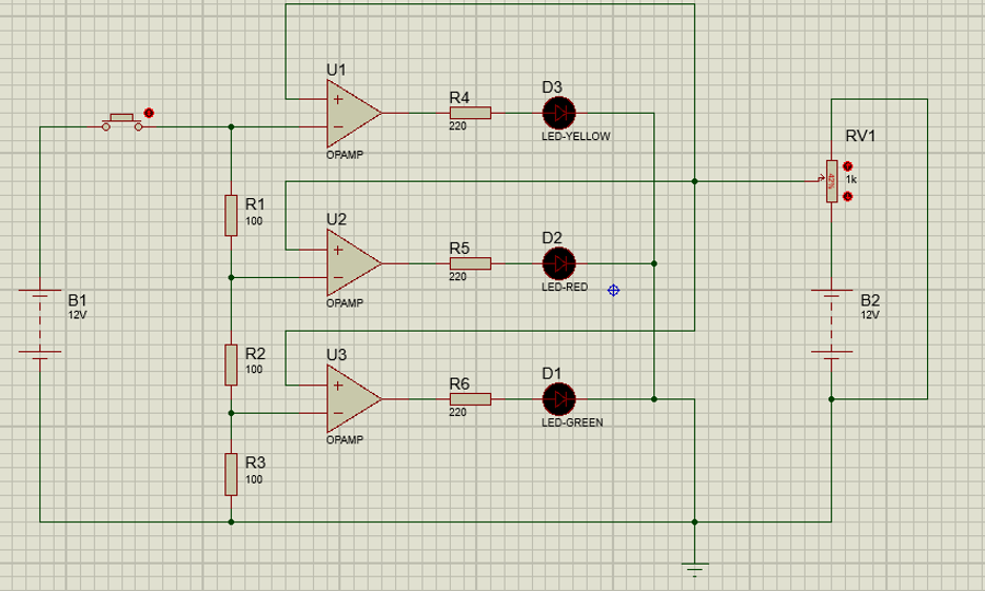
Step 4: Set the Reference Voltages
- Use a resistor network and adjustable resistor to establish the reference voltages.
- The adjustable resistor allows calibration so that the LEDs change state at the intended battery voltages.
- A stable voltage reference is preferable for accurate switching.
Step 5: Connect the LEDs
- Connect the yellow, green, and red LEDs to their respective indicator outputs.
- Install a current-limiting resistor in series with every LED.
- For example, a typical red LED with approximately 2V forward voltage operating at 10mA from a 12V source would require roughly a 1 kΩ resistor.
- Actual resistor values depend on LED specifications, available voltage, and comparator output design.
Step 6: Check the Circuit Connections
- Before supplying power, inspect the circuit for incorrect wiring, reversed LED polarity, and short circuits.
- Confirm that all comparator inputs operate within the permitted voltage range.
- Always consult the selected IC’s datasheet before powering the circuit.
Step 7: Power On and Calibrate
- Apply a controlled DC voltage and adjust the reference resistor until the indicators switch at the desired thresholds.
- A variable laboratory power supply is particularly useful because it allows precise testing of different voltage conditions.
Testing the Battery Level Indicator Circuit
Testing verifies whether the circuit responds correctly to changes in battery voltage.
Three operating conditions should be examined.
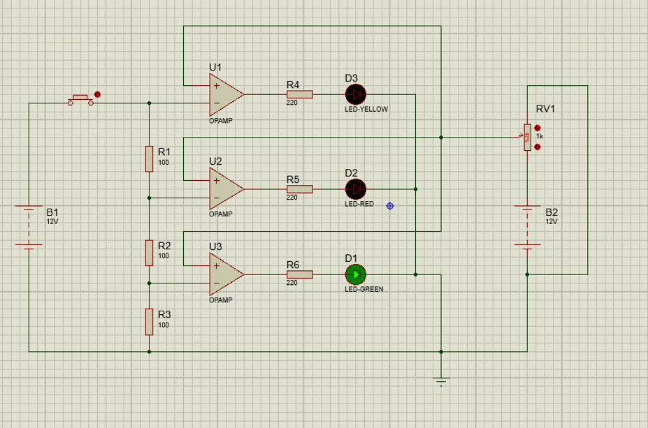
Test 1: Normal Battery Voltage
Set the supply voltage between the selected lower and upper thresholds. The green LED should illuminate while the yellow and red LEDs remain off. This confirms that the circuit recognizes its intended normal operating range.
Test 2: High Battery Voltage
Gradually increase the supply voltage beyond the upper threshold. The red LED should activate, while the other LEDs remain off. This verifies that the high-voltage comparison stage responds to the selected limit.
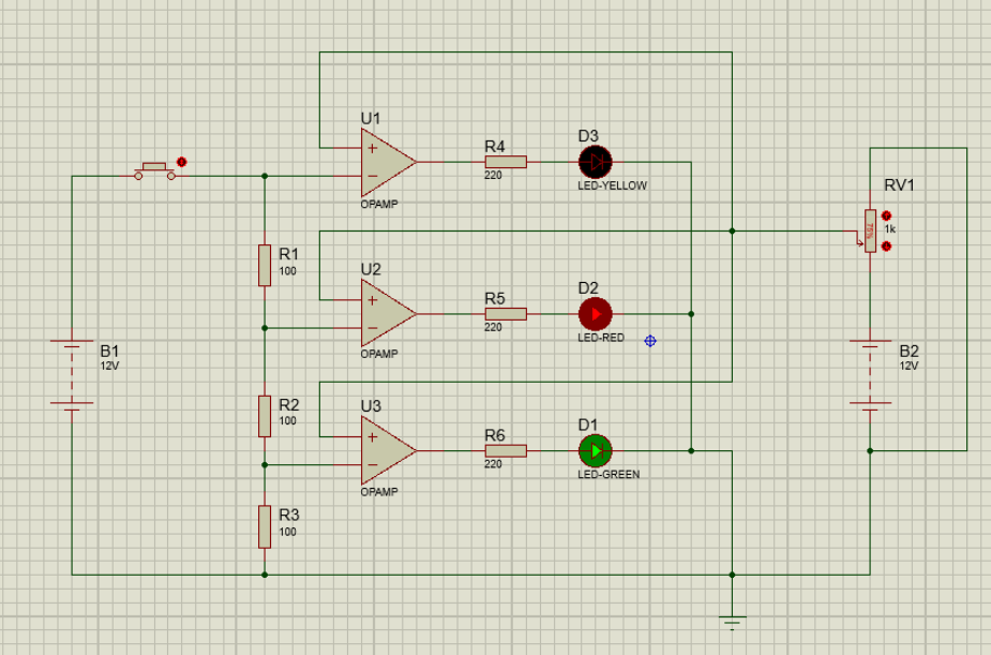
The red LED provides a warning only. It does not automatically disconnect the battery or provide overvoltage protection.
Test 3: Low Battery Voltage
Reduce the voltage below the lower threshold. The yellow LED should illuminate, indicating that the voltage has entered the low range. The green and red LEDs should remain off.
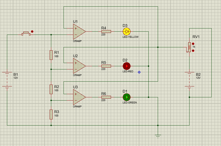
When all three tests produce the expected results, the indicator’s basic switching behavior has been verified. For improved accuracy, repeat the tests near each switching threshold.
Common Problems and Troubleshooting Tips
A battery indicator may occasionally produce incorrect or unstable LED readings.
- One common issue is an incorrectly adjusted reference voltage. This can cause an LED to activate too early or too late.
- Loose wiring, unsuitable comparator input voltages, or incorrect LED polarity may also prevent proper operation.
- Another issue occurs when the battery voltage fluctuates near a switching threshold. The LED may flicker rapidly between states.
- Adding a small amount of comparator hysteresis can reduce this problem by introducing slightly different switching points for rising and falling voltages.
Also remember that battery voltage changes under load. An indicator calibrated using an unloaded battery may respond differently when a motor or other device draws significant current.
Applications of Battery Level Indicator Circuits
A three-LED battery indicator can be useful in many low-voltage electronic applications. It can be incorporated into portable DIY electronics, battery-operated instruments, educational circuit projects, and small backup power systems.
Such indicators are particularly helpful where users need a quick visual voltage warning rather than continuous numerical measurements. The design can also be adapted for different battery voltage ranges by selecting suitable reference values, resistor ratios, and compatible components.
However, it should not replace a dedicated battery management system where overcharge, overdischarge, thermal protection, or cell balancing is required.
Frequently Asked Questions (FAQs)
1. How does a 12V battery level indicator circuit work?
A 12V battery level indicator uses voltage comparators to compare battery voltage with predefined reference values. Based on the measured range, a yellow, green, or red LED activates to indicate low, normal, or high voltage.
2. Can I build a battery level indicator without Arduino?
Yes. A battery indicator can operate entirely through analog components, including resistors, voltage comparators, LEDs, and an adjustable reference network. No Arduino, microcontroller, or programming is necessary.
3. Which IC is best for a battery level indicator?
The LM339 is one possible choice because it contains four voltage comparators in a single package. However, the best IC depends on supply voltage, power consumption, input range, and output requirements.
4. How can I adjust the battery indicator voltage thresholds?
You can adjust voltage thresholds by changing resistor values or using a variable resistor in the reference network. Measure the switching points with a multimeter and calibrate them according to your battery’s operating specifications.
5. Why does my battery indicator LED flicker?
LED flickering can occur when battery voltage fluctuates close to a switching threshold. Electrical noise and changing loads can make the comparator repeatedly change state. Proper filtering and comparator hysteresis can improve stability.
6. Does a battery voltage indicator show the exact battery percentage?
No. A simple voltage indicator displays predefined voltage ranges, not an exact battery percentage. Accurate state-of-charge estimation may require information about battery chemistry, current flow, temperature, and discharge history.
Conclusion
A 12V battery level indicator circuit using LEDs and voltage comparators is a practical electronics project for monitoring battery voltage By combining voltage dividers, adjustable reference voltages, comparator stages, and three colored LEDs, you can create an easy-to-understand visual monitoring system.
The most important steps are selecting appropriate thresholds, assembling the comparison circuitry correctly, and testing the low, normal, and high-voltage conditions. With careful calibration and suitable components, this simple circuit can provide useful voltage status information for a wide range of DIY battery-powered applications.
For more information and guidance, you can approach us through the Contact Us page.
